LIGHT OPERATING MODES
PERMANENT ILLUMINATION MODE
The illumination is recommended to be operated in switched (triggered) mode.
When used in continuous mode, the device is equipped with intelligent thermal protection.
If the internal temperature reaches a critical level, the illumination will automatically switch off temporarily.
Once the temperature drops to a safe level, operation is automatically restored. This feature protects
the LEDs from damage and significantly extends the service life of the illumination. For permanent
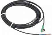
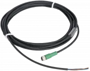
illumination bring the voltage of 24 V to the pin number 4 (black wire). The light is ON during the time when
the 24 V EN signal is activated. Use a PCL, camera or another binary signal source.
LIGHT TRIGGERING MODE
Light triggering mode saves energy and extends the lifetime of the light. To start using a triggering mode,
bring the pin number 4 (black wire) to a 24 V signal. The light is ON when a voltage signal is present at pin
number 4 then. Use a PCL, camera, or another binary signal source for triggering.
STROBE MODE
Light strobe mode significantly multiplies the maximum intensity of the light. The strobing function saves
energy, extends the light lifetime and in many cases improves the stability of the entire inspections system.
By applying a 24 V signal to pin 2 (white wire), you activate the strobe function. If 24 V is present on pin 2
and you simultaneously apply a 24 V signal to pin 4 (black wire), the light will operate in strobe mode.
Activating the signal on pin 4 triggers a strobe pulse with a fixed duration of 10 ms, during which the LED
diodes are powered with a maximum current of 2 A. The recovery time before the next pulse is 100 ms
- after this period, the pulse can be repeated.
Configuration
| Model series | Datasheet | 2D drawing | 3D model |
|---|---|---|---|
|
S-LP61-FLW-G1
(More variants)
|
Principles of use
Dimensions and weights
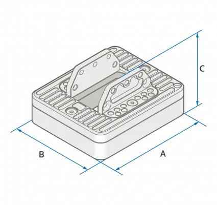
| Model series | A - Length (mm) | B - Width (mm) | C - Height (mm) | Weight (g) |
|---|---|---|---|---|
| S-LP61-FLW-G1 | 96 | 80 | 45 | 280 |
No question has been asked yet.
Your questions
You must log in to post questions.